In the realm of electrical engineering—particularly when working with high-voltage power supplies, transformers, printed circuit boards (PCBs), and medical or industrial-grade electronics—the safety of insulation systems is a top priority. Two critical parameters that ensure insulation integrity are clearance and creepage distance.
These terms are not just theoretical jargon; they directly relate to the physical spacing requirements between conductive parts to prevent electrical breakdowns, equipment failure, or catastrophic hazards such as fires and electric shocks.
Understanding the difference between clearance and creepage, knowing how to calculate them, and applying them properly in real-world designs is essential—not only for safety but also for regulatory compliance with standards like IEC 60664, UL 840, and IEC 62368-1.
This article dives into the definitions, differences, governing standards, and design considerations for clearance and creepage. Whether you’re designing a consumer electronics device or an industrial motor controller, these concepts form the backbone of insulation coordination.
1. What Are Clearance and Creepage?
At their core, both clearance and creepage distances are about preventing electrical failures, but they address two different types of risks.
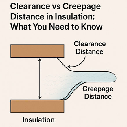
Clearance Distance:
Clearance is defined as the shortest distance through the air between two conductive parts. It is concerned with preventing arcing or flashover, which occurs when the voltage between two conductors exceeds the dielectric breakdown strength of air. Factors such as humidity, temperature, and especially altitude affect this air breakdown threshold.
- For example, in high-altitude environments, air is less dense and provides less dielectric strength, requiring greater clearance distances.
- Clearance is especially critical in circuits where high-frequency transients or overvoltage spikes (like surges from lightning or switching) are common.
Key Differences Recap:
|
Feature |
Clearance |
Creepage |
|
Path Type |
Through air |
Along insulating surface |
|
Main Risk |
Arcing/flashover |
Tracking/leakage current |
|
Influencing Factors |
Voltage, overvoltage category, altitude |
CTI, pollution degree, material group |
|
Control Strategy |
Physical spacing |
Surface contouring, slotting, coating |
2. Why Do We Need Two Distances?
The distinction between clearance and creepage isn’t arbitrary—it stems from two fundamentally different physical phenomena, each posing unique risks in electrical systems. Understanding these risks is crucial for designing robust insulation systems that remain safe and reliable over time.
Clearance: Protecting Against Dielectric Breakdown in Air
Clearance distance is designed to prevent arcing through the air. This phenomenon—also known as dielectric breakdown—occurs when the electric field between two conductive elements becomes strong enough to ionize the surrounding air. Once ionized, air becomes conductive, allowing a sudden high-energy spark or arc to jump between the conductors.
This risk is especially relevant in situations involving:
- Overvoltage transients, such as lightning strikes, load switching, or fault conditions.
- Altitude effects, where thinner air provides reduced insulation strength.
- High-frequency systems, where electric field gradients are intensified.
If the clearance distance is insufficient, even a small voltage surge can cause catastrophic damage, potentially igniting fires or destroying sensitive components.
Creepage: Preventing Surface Tracking and Leakage
Creepage distance is aimed at preventing tracking and leakage currents along the surface of insulating materials. Over time, environmental factors such as:
- Humidity
- Condensation
- Industrial pollution
- Dust and dirt accumulation
can degrade the surface integrity of insulating materials. This can lead to the formation of partially conductive paths, which progressively erode the material and eventually lead to a flashover or insulation failure—even without a large voltage spike.
Surface tracking is more insidious than arcing because it often develops gradually and may not be easily detectable until failure occurs. The material’s Comparative Tracking Index (CTI) and the environment’s pollution degree directly impact how much creepage is required.
Why It Matters
Because air and solid insulating surfaces behave so differently under stress, clearance and creepage require separate calculations and design strategies. While one guards against instantaneous arcing through the air, the other addresses the long-term risk of insulation breakdown due to contamination.
3. Key Influencing Factors:
When designing insulation systems, simply knowing the voltage isn't enough. The required creepage and clearance distances are influenced by a combination of electrical, environmental, and material-specific parameters. Each of these factors plays a distinct role in determining how much physical spacing is needed to ensure safety, reliability, and regulatory compliance.
1. Working Voltage
This refers to the maximum continuous voltage (AC RMS or DC) expected between two conductors under normal operating conditions. Higher working voltages naturally increase the risk of dielectric breakdown and tracking, demanding larger spacing. Both clearance and creepage distances scale with the working voltage.
2. Overvoltage Category (I to IV)
Defined by IEC standards, overvoltage categories reflect the likelihood and severity of voltage transients in a given installation:
- Category I – Electronic devices with internal protection (e.g., laptops).
- Category II – Appliances and portable equipment connected to fixed installations.
- Category III – Equipment permanently connected to distribution circuits (e.g., industrial motors, switchgear).
- Category IV – Equipment directly connected to the power source (e.g., utility meters, main service panels).
Higher categories require larger clearance distances due to increased transient voltage exposure.
3. Pollution Degree (1 to 4)
Pollution degree describes the environmental contamination level surrounding the insulation:
- PD1: Clean, dry, sealed environments—no pollution (e.g., hermetically sealed equipment).
- PD2: Ordinary environments with non-conductive pollution (e.g., offices).
- PD3: Conductive pollution or dry non-conductive pollution that becomes conductive when moist (e.g., factories).
- PD4: Persistent conductive pollution (e.g., outdoor high-voltage switchgear).
Higher pollution degrees mean a greater risk of tracking, requiring larger creepage distances.
4. Material Group (Based on CTI)
The Comparative Tracking Index (CTI) classifies insulating materials based on their resistance to electrical tracking. Materials are grouped as follows:
- Group I: CTI ≥ 600 (excellent tracking resistance)
- Group II: CTI 400–599
- Group IIIa: CTI 175–399
- Group IIIb: CTI < 175 (poor tracking resistance)
Materials with lower CTI require longer creepage distances to prevent tracking failures.
5. Altitude
At elevations above 2000 meters, the air density decreases, which reduces its dielectric strength. This makes arcing through air more likely, so clearance distances must be increased. Many standards provide correction factors or dedicated altitude adjustment tables for this purpose.
Design Implication
Engineers must assess all of these factors collectively during insulation coordination. A design suitable for a clean indoor lab might fail in an outdoor substation, even if the voltage remains the same. Applying the correct standards (like IEC 60664-1) ensures the distances selected are safe for the worst-case operating conditions.
4. Applicable International Standards
To ensure electrical safety and regulatory compliance, insulation designs must adhere to established international standards. These standards define the minimum required creepage and clearance distances based on key factors like voltage levels, pollution degree, and insulating material class.
Here are some commonly used standards:
- IEC 60664-1 – A foundational standard that outlines general principles for insulation coordination. It applies across a wide range of equipment and environments, offering detailed tables and guidelines for spacing based on system conditions.
- IEC 62368-1 – Geared specifically toward information and communication technology (ICT) and audio/video (AV) equipment. It replaces older standards like IEC 60950-1 and includes updated insulation requirements for modern devices.
- UL 840 & UL 60950-1 – These are North American standards that define insulation and spacing requirements for electrical and IT equipment. UL 840 complements other UL standards by providing detailed guidance on clearances and creepage for various voltage classes.
Each of these standards provides lookup tables and calculation rules that help engineers determine the minimum insulation distances required for safety and certification. Choosing the correct standard depends on your application, environment, and regional compliance needs.
5. Calculating Minimum Distances:
Calculating the appropriate creepage and clearance distances isn’t a guessing game—it’s a structured process based on standards and well-defined parameters. Here’s how engineers typically approach it:
- Determine the Working Voltage: Start with the maximum continuous AC or DC voltage expected between two conductors under normal operation.
- Identify the Type of Isolation: Decide whether the insulation is functional (basic operation), basic (for safety under normal conditions), or reinforced (provides double protection equivalent to two layers of basic insulation).
- Define the Pollution Degree: Assess the operating environment and select a pollution degree (1 to 4), as it significantly influences the creepage requirement.
- Select the Insulating Material Group: Based on the Comparative Tracking Index (CTI) of the material, classify it into Group I, II, IIIa, or IIIb. Materials with lower CTI values require longer creepage paths.
- Apply Altitude Correction (if above 2000 m): Higher altitudes reduce air density, increasing the risk of arcing. Use correction factors provided in standards like IEC 60664-1 to adjust clearance accordingly.
- Refer to Standard Tables: Use insulation coordination tables from standards (e.g., IEC 60664-1 or IEC 62368-1) to determine the exact minimum distances required for your case.
6. Design Techniques for Meeting Spacing Requirements
In practical circuit design, especially where space is limited, meeting the required creepage and clearance distances can be challenging. However, several proven engineering techniques can help achieve compliance without significantly increasing PCB size or cost.
When physical spacing is constrained, engineers often use the following strategies:
- Add Slots or Grooves in the PCB: By introducing cutouts or milled slots between high-voltage traces or components, the effective creepage path is lengthened along the surface, without changing the overall board layout.
- Apply Conformal Coating: A protective insulating layer (such as acrylic or silicone coating) over the PCB can reduce the pollution degree, lowering the creepage requirements in contaminated or humid environments.
- Use Insulation Barriers or Ribs: Plastic barriers or molded ribs between conductors help physically separate circuits, especially in enclosed modules or connectors, increasing creepage without increasing footprint.
- Route on Opposite PCB Layers: Traces carrying different potentials can be routed on opposite sides of a multilayer board, with ground or insulating layers in between. This effectively increases clearance and isolates signal paths.
These techniques are especially useful in compact, high-density designs, such as power adapters, embedded systems, and medical devices—where maximizing performance and safety in minimal space is key.
7. Safety & Certification Importance:
Failing to properly account for clearance and creepage distances isn’t just a design oversight—it can lead to serious safety hazards and regulatory setbacks. Insufficient spacing between conductive parts can result in:
- Electric Shock Risk: Inadequate insulation may allow high-voltage arcs to reach accessible parts, posing a direct hazard to users and maintenance personnel.
- Fire Hazards: Surface tracking or arc flash due to tight spacing can overheat components, potentially igniting surrounding materials and leading to equipment fires.
- Equipment Failure: Arcing, tracking, and insulation breakdown can damage components, cause short circuits, or lead to unpredictable system behavior.
- Legal and Regulatory Non-Compliance: Products that don’t meet international insulation standards (e.g., IEC, UL, CSA) may fail certification, resulting in delayed product launches, recalls, or market bans.
To avoid these consequences, manufacturers are required to carefully document and verify all insulation distances during design and testing. This documentation is critical for obtaining compliance marks such as CE, UL, or CSA, and for demonstrating due diligence in safety-critical applications.
8. Conclusion:
Clearance and creepage aren’t just technical jargon—they are critical pillars of safe and reliable electrical design. Whether you're developing a power converter, industrial automation system, or life-critical medical device, understanding and applying proper insulation distances helps ensure:
- User safety
- Product reliability
- Compliance with global standards
Always consult the relevant industry standards during design, and when uncertain, it’s wise to err on the side of caution. Overdesigning your insulation spacing may increase cost slightly—but the payoff in safety, certification success, and peace of mind is well worth it.
In high-voltage design, safety isn’t optional—it's engineered.